
Cutting Diagrams 101
- Igor Kondrasovas
- Aug 22, 2016
- 2 min read
A cutting diagram is a graphical representation of a board or sheet, containing all the necessary information to execute the cutting operations.
Some software and apps create cutting diagrams automatically. Usually this happens just after the optimization, a very complex combinatorial problem that can be solved relatively quickly by computers.
With a cutting diagram in hands, the machine operator can input the cutting sequence into the cutting equipment or even use the diagram as a guideline to operate traditional (non CNC) cutters.
"following the cutting diagram reduces the fabrication time, eliminate errors and gives predictability of the effort required to produce all parts."
Cutting Diagram Anatomy
The following image represents a cutting diagram of a sheet that will be cut using guillotine, band saws or even manually.
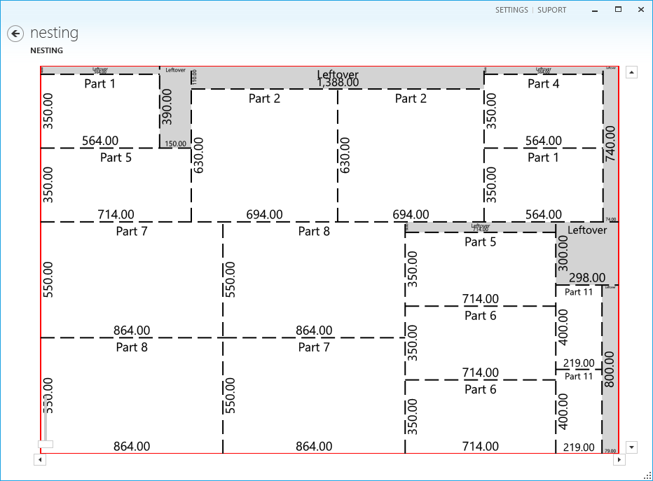
We can highlight some important information from the above cutting diagram:
1 - The red rectangle represents the sheet borders. They must be configured accordingly to the board size you have.
2 - The dashed lines represent the cutting operations that must be performed. Note that each cut goes from one edge to the other of the part being cut. Cuttings are not supposed to be partially made.
Obviously every cut results in the creation of two other pieces. Each one can be the final piece, a left over or a piece that will have to be cut again.
It is important to specify the kerf (or blade width) so the layout optimization can consider this material waste while finding the best layout for the parts.
3 - The part dimensions (width and length) can be use to orient the position of the cuttings in relation to the previous cut or the board.
At this stage, the use of adhesive labels are recommended for identification and traceability. The sooner you identify the parts, the better. When parts have similar dimensions, it may be difficult to distinguish them further in the assembly process.
4 - The grayed areas represent waste or left over parts. Depending on the size of the parts you produce, you may reuse some of these parts. However, it is recommended that you balance if its worth reusing leftovers or just wait a little to include more parts in the original plan.
The more different and the quantity of parts directly affect optimization level.
CNC machines
For cutting diagrams created for CNC machines like laser, plasma, water jet, routers and other CNCs, the cutting diagram must be present in a digital format that can be interpreted by Computer Aided Manufacturing (CAM) programs.
CAM programs will interpret the cutting lines and transform in tool path commands for a specific equipment.
DXF files or even g-code are the standard formats to be used send data to industrial cutters.
Other relevant information
Depending on the company workflow, other information can be necessary, like the edge banding indication, first cut indication, board margins, etc.
What about yourself? What additional information do you think a cutting diagram must have?


Comments