True Shape vs Rectangular Nesting
- Igor Kondrasovas
- May 15, 2017
- 2 min read
Updated: Feb 10, 2021
After so many years working with nesting software, we can see a clear separation on the market of true shape and rectangular nesting software products.
The difference arises form the cutting process used to produce the parts from the sheets. While true shape nesting software are commonly used for CNC cutters (router, laser, plasma, water jet, etc), cutting list software is usually found for guillotines, knifes, table saws, shears and other straight cutting tools.
We believe there should be no separation of products due to the difference of the cutting process. But it is important to understand the differences to make a better use of the product.
Rectangular Nesting
Rectangular nesting is traditionally know as "cutting list software" or "cut layout optimization program" instead of nesting programs. But all of them have the same goal: Minimize raw material waste.
As you may have noticed, while CNC machines can produce any 2D geometry (lines, arcs, etc), conventional machines can only cut from one edge to the other of the sheet.
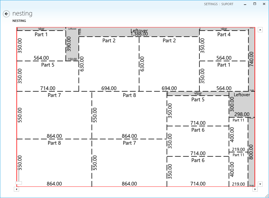
Please have a look the following image, representing a table saw cutting pattern. As you can see, all cuts represented by the dashed lines, goes from one edge to the other edge of the sheet.

Looking on the image, you see there is a clear sequence of cuts that must be done before the others, since every cut operation transforms a bigger piece in two smaller pieces.
Cutting from one edge to the other is a severe constrain for the layout optimizer, but it is fundamental to make the diagrams match the reality of the cutting equipment on the shop.
Rectangular nesting programs produce only rectangular parts. So there is no real need to use CAD files to specify part geometry. Only the width and length of the part are necessary.
This makes easy to rectangular nesting software import part list from other systems or spreadsheets, that is a big time-saving feature that minimize typing errors.
The waste form rectangular nesting are always rectangular parts. Depending on its dimensions and the size of parts usually produced, it can be reused in a future job.
True Shape Nesting
Usually true shape nesting solutions rely on CAD file (.DXF) to specify the part profile geometry. The nesting software must consider the real part geometry to maximize the number of parts in the sheet.

Although material efficiency is the goal, it is equally important to consider the machine costs. For this reason, true shape nesting programs also try to keep parallel lines as much as possible, so you can cut geometries of two different parts at the same time.
True shape nesting programs can also take advantage of the material on part holes, to increase efficiency. If you look on the following image, you sill the the hole is filled with other parts to reduce waste.

Help us!
Did you like this article. So share with your friend by email or using the social networks. We appreciate that!


Comments